Xochitl and I met this weekend to measure all of the yoyos we manufactured. We decided to measure the outer diameter of the yoyo that is involved in the snap fit with the ring, as this is the most vital dimension for functionality. The target dimension was 2.3in.
We used two different calipers in order to speed up the process. However, this gave us inconclusive results as the two calipers gave different readings. One set consistently gave readings above 2.3in, and the other consistently gave readings below 2.3in. Although the two calipers gave different readings, it is important to note that the difference in readings between the two are approximately 10-thousandths of an inch, which is an incredibly small difference.
Results are tabulated here. Results to take note of are Percent Dev and Dev Length.
The most important conclusion from our measurements is that all 6 processes we tested in lab produced yoyo's within 0.3% of the target dimension of 2.3in, which is 7-thousandths of an inch. Because this dimension is involved in the snap fit, we believe that it is better to be slightly larger than 2.3in rather than smaller. Process 5 produced the largest yoyo's, as measured by both sets of calipers.
Depending on which caliper you trust, process 5 made yoyo's
0.14% smaller than 2.3in
or, 0.20% larger than 2.3in
We will be discussing these results with Dave and Dave later in the week to determine which process to use in the final production run.
The 1/8" headed pins we ordered from McMaster-Carr arrived. They fit onto our injection molded body part. To accomplish this I used a vice to press fit the pin into the center hole. This press fit holds very sturdy.
I just want to make sure that everyone else is up to date with what Eddie and I have done with the body. Hope everyone had a great spring break!
Wednesday, March 19th
Eddie and I made the shaft that holds the nut that gets embedded into the body when we are injection molding.
We were given the shafts as pictured in the top left. Using the lathe we cut the shafts to our desired dimensions. It was very important that when we placed the shaft into the center hole of the cavity mold, it was flush with the mold. Dave advised us to make four shafts to help speed up our production rate when are are injection molding.
Friday, March 21st
Friday morning we went to our first injection molding appointment. We quickly found that air was getting trapped in the plastic. This lack of a gas vent was giving us short shots on all of our parts.
In order to pin-point the problem, we increased the injection pressure to make the plastic burn in the problem area.
To fix the problem, decided to drill three 0.001" deep slots to allow the air to escape. We drew our initial design on the mold and then went into lab to do the Mastercam. We finished the Mastercam, however, it was too late for us to use the mill that day.
Even though we had a problem area, we wanted to see if our snap-fit worked with our team's rings. We found that they fit beautifully.
On Monday, Eddie and I had our optimization appointment. However, we first needed to fix our mold. After a minute on the mill, our air channels were on the cavity mold.
We happily found that this fixed our problem. There was a tiny imperfection, however the ring would be covering it, so it was perfectly fine.
The point of this appointment was to optimize the production process of the injection molded body. We did 6 batches of 8 pieces, where each batch used different machine parameters. This process is summarized below:
Batch 3
Injection Hold
Injection Hold Pressure Profile (psi):
500 600 700 800 750
700 600 575 575 550
Injection Hold Time: 8 sec
Cooling Time: 25 sec
Set Screw Feed Stroke: 2.7in
Injection Boost
Injection Speed Profile
5.5 5.5 5 4 4
3.5 3 2 1 0.5
Injection Boost Pressure: 1600psi
Screw Feeding
Screw Feed Delay Time: 2 sec
Ejector
Ejector Counter: 2
Mold
Ejector Pin Length: 5.695in
Total Shim Thickness: 0.056in
Batch 4
Settings of Batch 3
Injection Hold Pressure Profile (psi):
700 800 900 1000 950
900 800 775 775 750
Batch 5
Settings of Batch 4
Injection Hold Time: 12 sec
Batch 6
Settings of Batch 4
Injection Boost Pressure: 1400psi
Batch 7
Settings of Batch 4
Injection Boost Pressure: 1800psi
Batch 8
Setting of Batch 4
Cooling Time: 30 sec
We found it very interesting that the bodies would occasionally burn. To us, it almost seemed independent of the parameters we were changing. The yo-yo's circled in red are the ones that burned.
Due to the fact that the bodies were still shrinking, we could not measure them right after we were done. We will be meeting later this week to measure all of the pieces to determine which parameter settings yield the best results in the body dimensions.
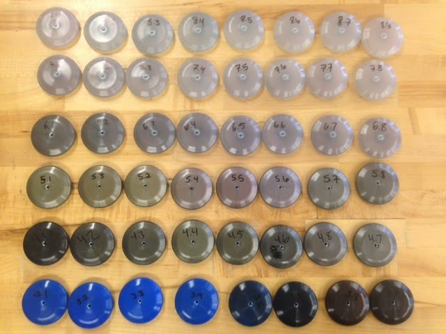
Sebastian and I (Delphine) ran the optimization run for the ring this afternoon. Our pieces do a nice color scheme of red to blue through some weird purples.
We played with cooling time and injection hold time.
We'll need to make measurements and decide on optimal parameters later this week.
Sad thing: we need to use fluid on the mold every 10-15 pieces or they don't fall off properly and you have to pry them off with a screwdriver, which is hard!
The acrylic, pins and a sheet of thermoform stuff (although I couldn't remember what thickness it was supposed to be, so I hope I took the right one) are in our bin now in addition to all of our 50 optimization run rings.
On Friday Eddie and I completed the the mill and lathe work for the molds. I've attached pictures below. We are setting an appointment during our lab on Wednesday to make the shafts.
No pictures because I forgot, but they're all set.
Also - FYI, we shouldn't be using lab time to actually make parts until all teams have their molds machined. So if we want to mold/thermo form we have to make an appointment.
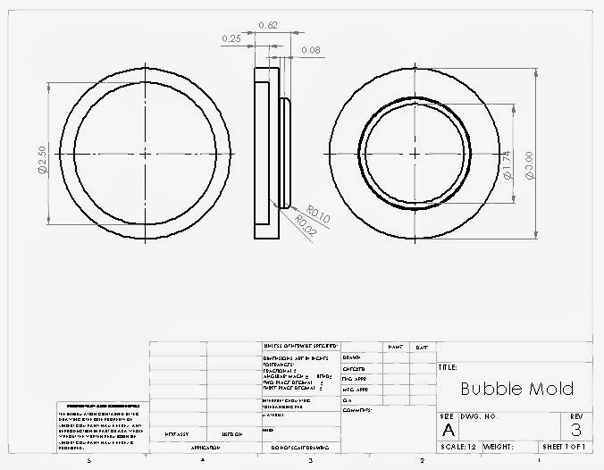
Hello all. I made a mold for thermoforming the "Bubble", that is, the clear outer casing of the yo-yo that covers the clock face features.
The pertinent files are in the Dropbox>Timeturner>Bubble. Revision 3 is the up-to-date model, which fixed the trench in the face of the Revision 2 core.
Machining appointment with Rashed during lab time Wed. March 12, 2014.
Great progress, everyone.
I will make sure to go into lab to put everything in the dropbox folder. Right now the G-Code and Mastercam toolpaths for the lathe and mill are saved on my Z-Drive.
What is shared with you guys:
The Solidworks model and dimensioned drawing (dropbox folder)
Process plan for lathe and mill (google drive)
The finished deliverable report (google drive)
I've printed out our deliverable and I will be submitting it in class tomorrow.
Delphine, Sebastian and I met today to discuss changes to our design, and
We were worried about the hands of our clock for a while, with two major concerns:
That, given enough clearance, a hand could snag on another.
That the hands would sag and be overlapping at all times.
After some back-of-the-envelope calculations, the first concern turned out to be dismissible as unlikely. The second concern was solved by deciding to change the hand design to be one piece of 1/8" acrylic that included both hands, instead of two 1/16" pieces that were two individual hands.
We also designed and wrote the tool paths/Gcode for both the cavity and core molds.
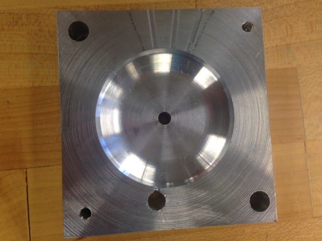
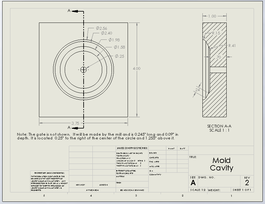
Here's an image of the cavity mold:
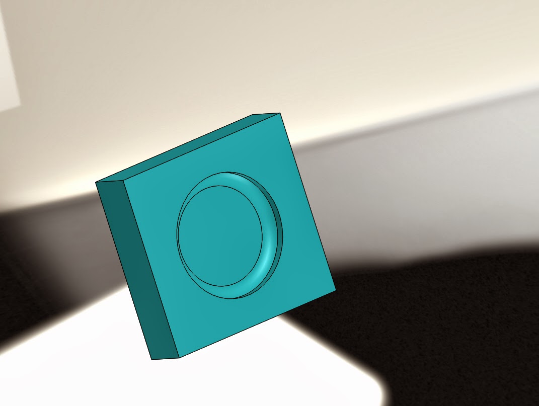
Here's the core mold
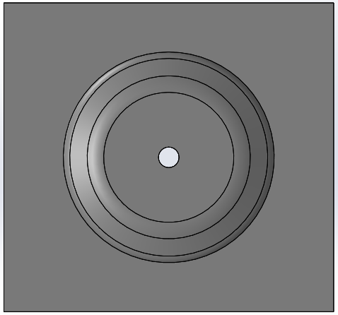
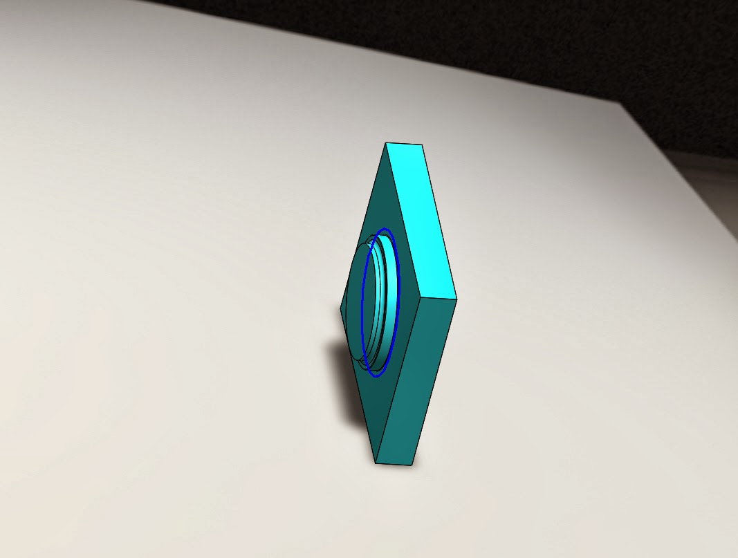
A cross-sectional view of the two of them together:
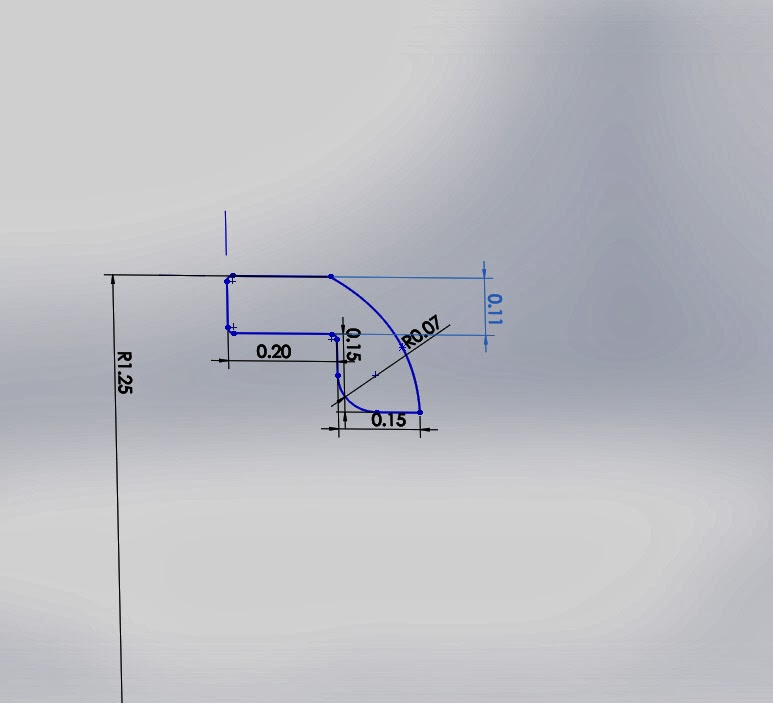
We ended up having to change the ring's design due to complications with
the mold. A fillet was added in one location, and removed in another.
A sketch of the ring's cross-section, denoting the changes:
The ring itself is black, which makes it difficult to see the dimensions on it.
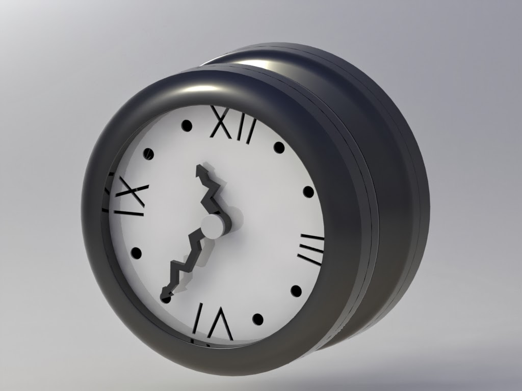
Glad to see some results after a long day of work!
Xochitl and I met today to make revisions on the yo-yo body. Several changes were made to the design:
Re-dimensioned the center hole for the nut: 0.5" diameter, and made the hole slightly longer
Re-dimensioned the center hole for the press fit, such that there is 0.005" clearance for the pin to be press fit
Removed some of the center material to keep uniform thickness
With the design revised, we made the molds. Xochitl determined the percent shrinkage we expect to see based on taking measurements from previous yo-yos with similar features. We determined a shrinkage of about 2.3%. To make the molds on Solidworks we followed a tutorial:
Here are our molds:
The next steps to take are to make dimensioned drawings of the two molds, and to Mastercam the tool paths to manufacture the molds.
.JPG)


.jpg)
.jpg)


